The cluster creation form requires a configured network, subnet, and SSH key before it can be submitted. Setting these up before opening the form avoids navigating away mid-creation. Networks and subnets can be prepared under GPU Cloud > Networking > Networks; SSH keys under GPU Cloud > SSH Keys.
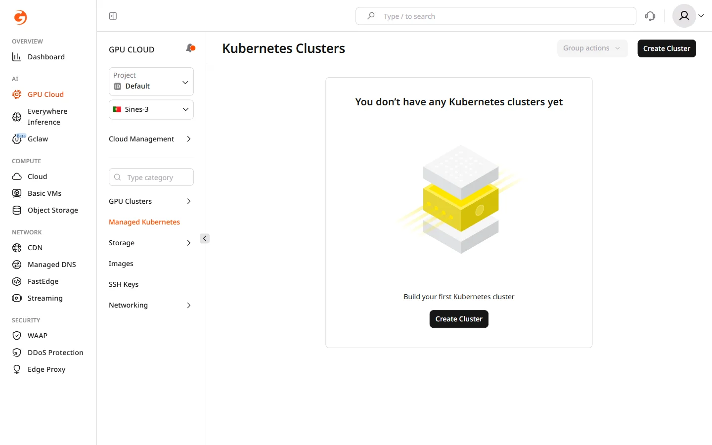
- In the Gcore Customer Portal, navigate to GPU Cloud.
- In the sidebar, select Managed Kubernetes.
- Click Create Cluster.
Step 1. Select region
In the Region section, select the data center location for the cluster. Region choice affects GPU model availability, VAST Storage support, and network latency for workloads.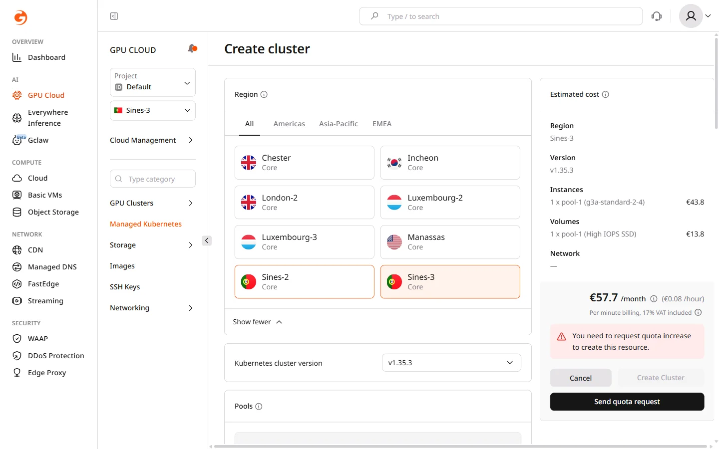
Changing the region after configuring other settings resets all form values.
Step 2. Select Kubernetes version
In the Kubernetes cluster version dropdown, select the version for the cluster. The latest stable version is selected by default and is recommended unless workloads require a specific version for compatibility. Kubernetes versions can be upgraded after cluster creation, but a downgrade is not supported.Step 3. Configure node pools
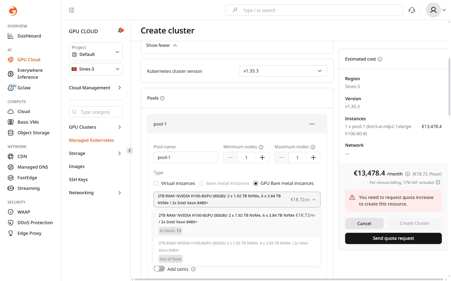
Node pools define the worker nodes where workloads run. Each pool has its own instance type, scaling limits, and volume configuration. A cluster can have multiple pools with different instance types, allowing GPU workloads and general services to run side by side.- In the Pools section, configure the default pool or click Add pool to add another.
- Enter a Pool name.
- Set Minimum nodes and Maximum nodes. Set the minimum above zero if the pool must always have running nodes — a minimum of zero allows the autoscaler to scale the pool down completely when idle.
- Select the node Type:
| Type | Description | Use case |
|---|---|---|
| Virtual instances | Standard VMs | Development, testing, general workloads |
| Bare metal instances | Dedicated physical servers | High-performance CPU workloads |
| GPU Bare metal instances | NVIDIA GPU servers with built-in NVMe storage | Model training, inference at scale |
Bare metal instances are not available in all regions. If the option is unavailable, switch to a region that supports bare metal, such as Luxembourg-2.
- Select a Flavor. Each flavor card shows specifications, storage, and hourly pricing. GPU Bare metal instances include built-in NVMe storage — no separate volume configuration is required.
- For Virtual and Bare metal instance types, configure the boot volume: select a Volume type and set Size to a minimum of 50 GiB. High IOPS SSD reduces latency for I/O-intensive workloads.
- Select a Placement policy. Anti-affinity soft instructs the scheduler to place nodes on different physical hosts when possible, reducing the impact of a single host failure on pool availability. If the cluster does not have enough physical hosts to honor the policy, nodes are still scheduled.
-
(Optional) Configure additional node settings:
- Add labels — Kubernetes labels attached to all nodes in the pool. Labels are used in pod specs to target specific pools with
nodeSelectoror node affinity rules. - Add taints — taints prevent pods from being scheduled on pool nodes unless the pod explicitly tolerates the taint. Use taints to dedicate GPU pools exclusively to GPU workloads.
- Autohealing nodes — enabled by default; the cluster monitors node health using Kubernetes node conditions and automatically drains and replaces nodes that become unhealthy.
- Public IPv4 address — assigns a public IP to each node. When enabled, private network selection becomes optional and the cluster is created in the public network. IPv6 dual-stack is available for nodes in the public network.
- Add labels — Kubernetes labels attached to all nodes in the pool. Labels are used in pod specs to target specific pools with
- To configure container runtime settings, environment variables, and resource limits, click the … menu in the pool header and select Configure settings.
Step 4. Configure CNI provider
The Container Network Interface (CNI) provider manages pod-to-pod and pod-to-service networking within the cluster. The CNI choice affects network throughput, observability capabilities, and compatibility with network policies.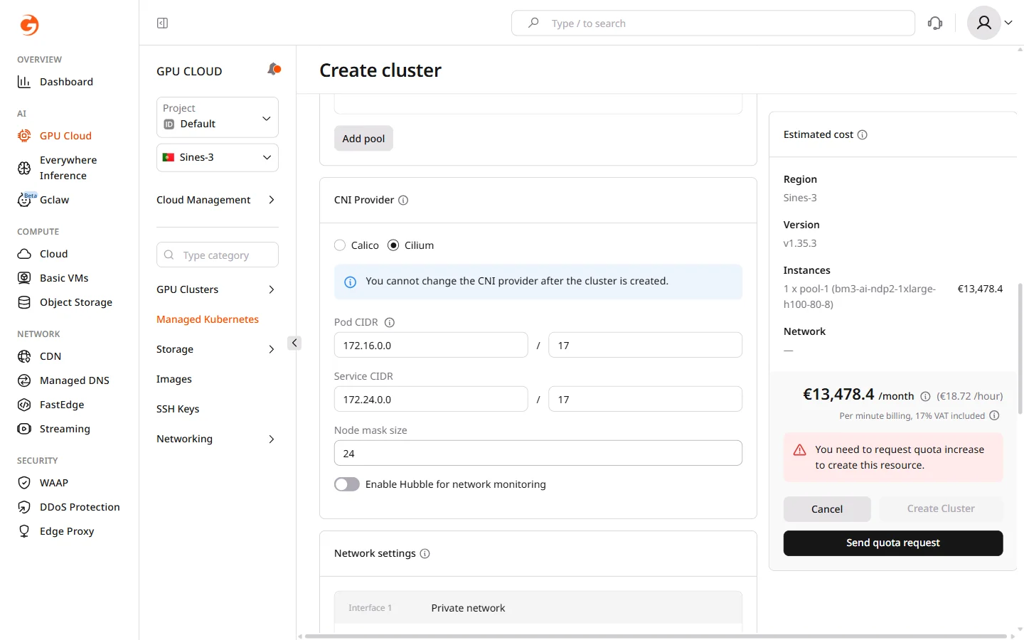
- Select a CNI provider:
| Provider | When to use |
|---|---|
| Calico | Familiar iptables-based networking; broad compatibility with existing tooling |
| Cilium (default) | eBPF-based networking with higher throughput and built-in flow observability via Hubble |
The CNI provider cannot be changed after cluster creation.
- Configure network ranges. Change the defaults only if they conflict with existing networks — for example, if a VPN or peered network uses overlapping addresses:
- Pod CIDR: IP range assigned to pods (default:
172.16.0.0/17). Each node carves a subnet from this range based on the node mask size. - Service CIDR: IP range assigned to Kubernetes services (default:
172.24.0.0/17). - Node mask size: subnet size allocated per node (default:
/24, which allows up to 254 pods per node). A smaller mask allows more pods per node; a larger mask allows more nodes but fewer pods each.
- Pod CIDR: IP range assigned to pods (default:
- If Cilium is selected, optionally enable Hubble for network monitoring to capture and visualize network flows between pods and services.
Step 5. Configure network settings
In the Network settings section, assign the private network interface for cluster nodes. All nodes join this network and communicate with each other through it.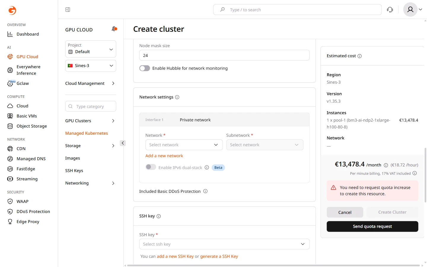
- Select an existing Network or click Add a new network to create one.
- Select a Subnetwork within the chosen network.
Step 6. Add an SSH key
In the SSH key section, select the SSH key to use for node access. The key is installed on all nodes in the cluster and is used for direct OS-level access — for example, to debug node issues or inspect container runtime logs. Select an existing key from the dropdown or click Add a new SSH Key to add one. Keys can also be managed under GPU Cloud > SSH Keys.Step 7. Name the cluster
In the Cluster name field, enter a name or use the auto-generated default. The name identifies the cluster in the portal, in kubeconfig files, and in audit logs.Step 8. Configure logging
The Logging section enables log collection from cluster nodes and workloads, storing them in OpenSearch Dashboards for analysis and debugging. Logging is a paid feature.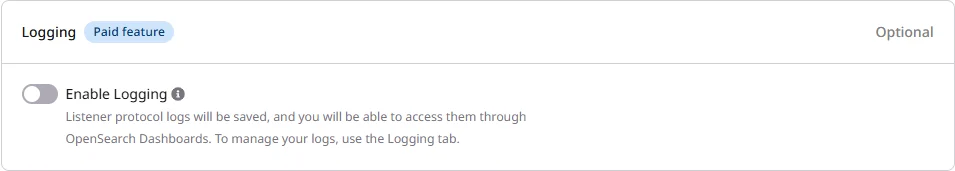
Step 9. Configure advanced settings
The Advanced settings section contains optional cluster-level configuration. These settings can be changed after cluster creation from the cluster overview page.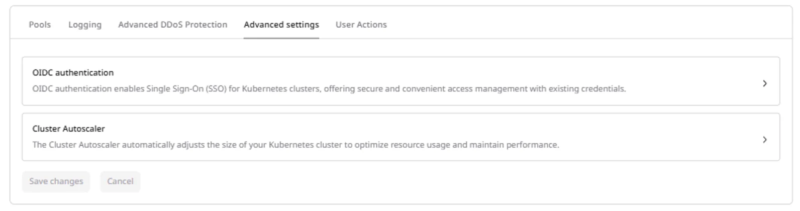
- OIDC authentication — configure Single Sign-On for Kubernetes API access using an external identity provider such as Okta, Azure AD, or Keycloak. When configured, cluster users authenticate with their identity provider credentials rather than kubeconfig tokens. Set the issuer URL, client ID, and claim settings.
- Cluster Autoscaler — tune autoscaling behavior including how frequently the cluster checks for pending pods, how long a node must be underutilized before removal, and grace periods for pod termination.
Step 10. Review cost and create
The Estimated cost panel on the right shows monthly and hourly pricing for all configured resources, broken down by instances, volumes, and network, including VAT.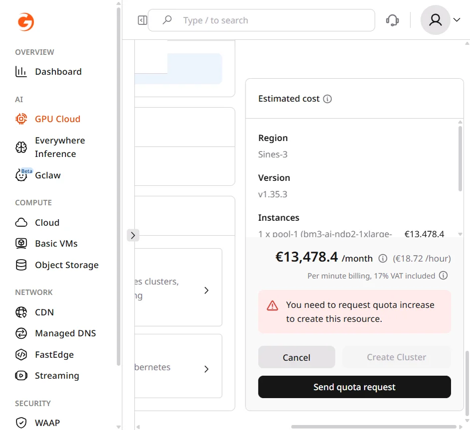
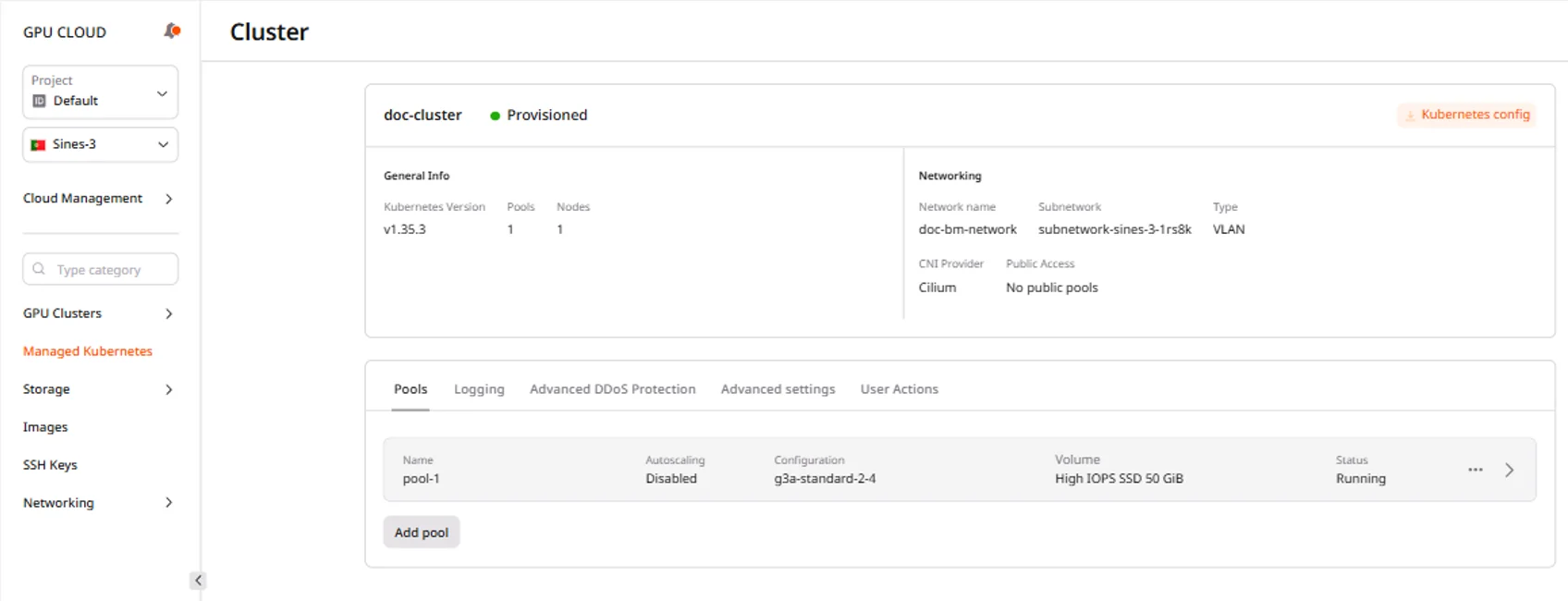
After cluster creation
When the cluster reaches Provisioned status, it appears in the Managed Kubernetes list with a green Provisioned badge.
Connect to the cluster
The kubeconfig file enables kubectl connections to the cluster. Download it after the cluster reaches Provisioned status:- Navigate to the cluster overview page.
- Click Kubernetes config.
- Save the downloaded
k8sConfig.ymlfile.